Product Description
CK6130 CNC Lathe Machine
Product Application:
This machine is widely used in processing the electrical appliance, instrumentation, automobile, motorcycle, fastener, bearing,photographic and film machinery, hardware tools, watches, glasses, stationery motors, valves, gas pipe and other high precise and complex components. It is the ideal high efficient equipment in hardware machinery industry.
Product Feature:
1. This series lathe has compact structure, pleasant appearance, large spindle torque, high rigidity, stable and reliable performance, and excellent accuracy retention.
2. Bedstock optimization design is suitable for turning disc and shaft parts. It can process straight line, arc, metric and British threads and multi-head threads. It can also be used for turning disc and shaft parts with complex shape and high precision.
3. The lathe guideway and saddle guideway adopt the hard guideway of special material. After high frequency quenching, they are super hard and wear-resistant, durable and have good processing accuracy.
4. Use domestic famous ball screw and high precision screw bearing.
ACR machine tool product series:
Slant bed CNC lathes | linear rail flat bed CNC lathes | 1 piece casting bed box way CNC lathes | vertical machining center
| Specifications | Units | CK6130 |
| Max.swing over bed | mm | 300 |
| Max. swing over cross slide | mm | 100 |
| Max. processing length | mm | chuck 200/collet 320 |
| X/Z axis travel | mm | 300/350 |
| Spindle nose | A2-5 | |
| Spindle bore | mm | 48 |
| Bar capacity | mm | 40 |
| Max.Spindle speed | rpm | 2500 |
| Chuck size | mm | 160 |
| Spindle motor | kw | 4 |
| X/Z axis repeate positionsing accuracy | mm | ±0.005 |
| X/Z axis feed motor torque | N.m | X:4 ; Z:4 |
| X/Z axis rapid feed speed | mm/min | X:8 ; Z:10 |
| Tailstock sleeve diameter | mm | 52 |
| Tailstock sleeve travel | mm | 90 |
| Tailstock taper | # | MT4 |
| Tool post type | 4 position electric tool post | |
| Cutting tool shape size | mm | 16*16 |
| Machine dimension(L*W*H) | mm | 1600*1100*1650 |
| Net weight | Kg | 1250 |
Technical parameters:
Machine tool structure characteristics and functional requirements
1.1 This series of machine tools is the company’s main export mature product. The whole machine has a compact structure, beautiful appearance, large spindle torque, high rigidity, stable and reliable performance, and excellent accuracy retention.
1.2 Optimized design of the headstock, suitable for turning of disc and shaft parts. It can process straight, arc, metric and inch threads, and multi-threaded. It is suitable for turning discs and shafts with complex shapes and high precision requirements. Parts Processing.
1.3 Both the machine tool CZPT rail and the sliding saddle CZPT rail adopt hard CZPT rails made of special materials. After high frequency quenching, they are super hard and wear-resistant, durable, and have good machining accuracy retention.
1.4 CNC system adopts FANUC system, domestic famous ball screw and high-precision screw bearing.
1.5 The spindle adopts high-precision spindle bearing set and has been precisely assembled and dynamically balanced to ensure that the spindle has high precision, low noise and strong rigidity.
1.6 Each lubrication point adopts a forced automatic lubrication device for fixed-point and quantitative lubrication of the lead screw and CZPT rail. When there is an abnormal state or the amount of oil is insufficient, a warning signal is automatically generated.
1.7 Standard configuration adopts domestically made three-jaw self-centering manual chuck.
1.8 The CZPT rail is equipped with a scraping device to prevent the CZPT rail from being corroded by iron filings and coolant, and to facilitate the cleaning of the iron filings.
Main technical parameters, configuration table
| Project | Unit | CK6130 | ||
| Maximum turning diameter of bed | mm | Φ300 | ||
| X-direction rail span | mm | 160 | ||
| Z-direction rail span | mm | 230 | ||
| Maximum turning diameter of slide | mm | Φ100 | ||
| Center distance | mm | 350 | ||
| Maximum turning length | mm | 230 | ||
| Center height | From bed | mm | 150 | |
| Off the ground | mm | 1065 | ||
| Spindle hole diameter | mm | Φ48 | ||
| Bar diameter | mm | Φ45 | ||
| With hollow chuck rod through hole | mm | Φ40 | ||
| Spindle end type | A2-5 | |||
| Chuck | mm | 160 | ||
| Spindle speed limit | rpm | 2500 | ||
| Diameter of tailstock sleeve | mm | Φ52 | ||
| Taper of inner hole of tailstock sleeve | No | MT4# | ||
| Tailstock sleeve stroke | mm | 80 | ||
| Tailstock | Manual | |||
| Electric tool rest | set | 4 | ||
| Knife square size | mm | 20×20 | ||
| Lead screw | X | mm | FDC2506-P3 | |
| Z | mm | FDC3210-P3 | ||
| X/Z direction rapid traverse speed | m/min | 6/10 | ||
| X stroke | mm | 280 | ||
| Minimum setting unit | mm | 0.001 | ||
| main motor power | KW | 4 | ||
| Machine Net Weight | Kg | 1700 | ||
| Dimensions (length×width×height) | mm | 2200×1160×1620 | ||
| Technical parameter | Unit | CK0640 |
| Maximum turning diameter of bed | mm | Φ230 |
| The maximum turning diameter of the pallet | mm | Φ100 |
| Z/X maximum travel | mm | 260/220 |
| Spindle through hole diameter | mm | Φ48 |
| Through hole diameter of draw tube | mm | Φ41 |
| Workpiece clamping method | Pneumatic clamping | |
| Z/X axis servo motor | N.M | 4/4 |
| Z/X axis rapid traverse speed | m/min | 6/7 |
| Spindle maximum speed | rpm | 2800 |
| Tool holder size | mm | 20*20 |
| Tool holder repeatability | mm | ≤0.005 |
| Frequency converter | kw | 5.5 |
| main motor power | kw | 4 |
| Tool holder method | row of knives | |
| Machine weight | kg | 1500 |
| Machine size | mm | 1610*1180*1600 |
Machine accuracy
| Test items | Standard tolerance(mm) |
| Periodic axial movement of the spindle | 0.005 |
| Radial runout of the positioning cone of the spindle chuck | 0.005 |
| Position accuracy | ±0.005 |
| Diameter consistency | 0.01/150 |
| Flatness | 0.571/φ300 |
| Thread pitch product error | 0.571/100 |
| Surface roughness | Ra1.6μm |
Main configuration list
| Name | Specification model | Quantity |
| Control System | FANUC | 1 |
| Spindle structure | Stepless speed regulation | 1 |
| Screw bearing | Flange bearing | 1 |
| Spindle motor | 4 KW | 1 |
| Ball screw | 2506/3210 | 1 |
| Tool holder | Four-station electric tool post | 1 |
| Automatic lubrication device | RBCLB-2BZK | 1 |
| Three-jaw manual chuck | K11160 | 1 |
| Cooling pump | P=90W | 1 |
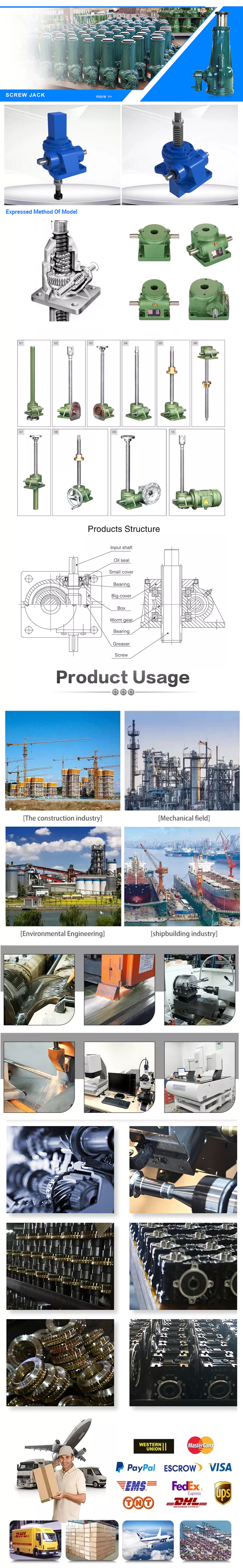
Packing:
Shipments:
Company introduction:
ZheJiang ACR Machine Tool Co., Ltd. is an enterprise integrating product design, research and development, manufacturing and sales. Mainly produce and operate CNC lathes, CNC milling machines, vertical machining centers, horizontal machining centers, gantry machining centers, ordinary lathes, vertical drilling machines, radial drilling machines, ordinary milling machines, metal band saws, planers, surface grinders, etc. More than 50 series of products.
ACR is committed to the innovation of machining technology and solutions, and has become a domestic high-quality supplier of CNC lathes, vertical machining centers, horizontal machining centers, drilling centers, CNC gantry milling and boring machines and other products for just a few years. It was rated as “national high-tech enterprise”, “ZheJiang science and technology small and medium-sized enterprise”. The company has passed the “ISO90001 international quality system”, “ISO14001 environmental quality system certification”, the enterprise credit rating is “AAA”.
ACR has introduced and implemented the CE system and the on-site 5S management mode for a long time. We do a meticulous job in each link,and strictly manage each production process.We have won many national and provincial awards. ACR brand CNC lathes, machining centers, CNC gantry milling and boring machines, drilling centers, etc. have been awarded the titles of “national machinery industry high-quality brand products” and ZheJiang Province famous brand products. Adhering to the concept of “creation and innovation, common prosperity and sharing”, ACR has always pursued the goal of first-class enterprise, first-class product, first-class service and first-class benefit”, strive to “create greater value” for our customers, and strive to build a CNC machine tool industry chain group company.
FAQ:
1:How can I choose the most suitable machines ?
A: Please tell me your specifications ,we can choose the best model for you , or you can choose the exact model .
You can also send us the products drawing ,we will choose the most suitable machines for you .
2: What’s your main products of your company?
A: We specialized in all kinds of machines ,such as CNC Lathe Machine ,CNC Milling Machine ,Vertical Machining Center ,Lathe
Machines ,Drilling Machine ,Radial Drilling Machine ,Sawing Machine ,Shaper machine and so on .
3: Where is our factory located? How can I visit there?
A : Our factory is located in HangZhou City ,ZheJiang Province,277500 China. You are warmly welcomed to visit us.
4. What is your trade terms?
A : FOB, CFR and CIF all acceptable.
5: What’s the Payment Terms ?
A : T/T ,30% initial payment when order ,70% balance payment before shipment ;
Irrevocable LC at sight .
5: What’s the MOQ?
A: 1 set .(Only some low cost machines will be more than 1 set )
| After-sales Service: | Three Packs of Service |
|---|---|
| Warranty: | 1year |
| Application: | Metal |
| Process Usage: | Metal-Cutting CNC Machine Tools, CNC Non-Conventional Machine Tools, Metal-Forming CNC Machine Tools |
| Movement Method: | Contour Control |
| Control Method: | Closed-Loop Control |
| Customization: |
Available
| Customized Request |
|---|

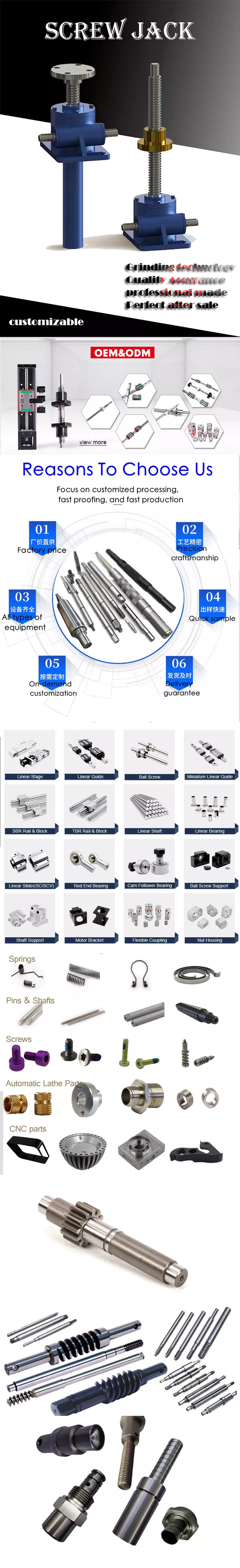
What Are Screw Shaft Threads?
A screw shaft is a threaded part used to fasten other components. The threads on a screw shaft are often described by their Coefficient of Friction, which describes how much friction is present between the mating surfaces. This article discusses these characteristics as well as the Material and Helix angle. You’ll have a better understanding of your screw shaft’s threads after reading this article. Here are some examples. Once you understand these details, you’ll be able to select the best screw nut for your needs.
Coefficient of friction between the mating surfaces of a nut and a screw shaft
There are two types of friction coefficients. Dynamic friction and static friction. The latter refers to the amount of friction a nut has to resist an opposing motion. In addition to the material strength, a higher coefficient of friction can cause stick-slip. This can lead to intermittent running behavior and loud squeaking. Stick-slip may lead to a malfunctioning plain bearing. Rough shafts can be used to improve this condition.
The two types of friction coefficients are related to the applied force. When applying force, the applied force must equal the nut’s pitch diameter. When the screw shaft is tightened, the force may be removed. In the case of a loosening clamp, the applied force is smaller than the bolt’s pitch diameter. Therefore, the higher the property class of the bolt, the lower the coefficient of friction.
In most cases, the screwface coefficient of friction is lower than the nut face. This is because of zinc plating on the joint surface. Moreover, power screws are commonly used in the aerospace industry. Whether or not they are power screws, they are typically made of carbon steel, alloy steel, or stainless steel. They are often used in conjunction with bronze or plastic nuts, which are preferred in higher-duty applications. These screws often require no holding brakes and are extremely easy to use in many applications.
The coefficient of friction between the mating surfaces of t-screws is highly dependent on the material of the screw and the nut. For example, screws with internal lubricated plastic nuts use bearing-grade bronze nuts. These nuts are usually used on carbon steel screws, but can be used with stainless steel screws. In addition to this, they are easy to clean.
Helix angle
In most applications, the helix angle of a screw shaft is an important factor for torque calculation. There are two types of helix angle: right and left hand. The right hand screw is usually smaller than the left hand one. The left hand screw is larger than the right hand screw. However, there are some exceptions to the rule. A left hand screw may have a greater helix angle than a right hand screw.
A screw’s helix angle is the angle formed by the helix and the axial line. Although the helix angle is not usually changed, it can have a significant effect on the processing of the screw and the amount of material conveyed. These changes are more common in two stage and special mixing screws, and metering screws. These measurements are crucial for determining the helix angle. In most cases, the lead angle is the correct angle when the screw shaft has the right helix angle.
High helix screws have large leads, sometimes up to six times the screw diameter. These screws reduce the screw diameter, mass, and inertia, allowing for higher speed and precision. High helix screws are also low-rotation, so they minimize vibrations and audible noises. But the right helix angle is important in any application. You must carefully choose the right type of screw for the job at hand.
If you choose a screw gear that has a helix angle other than parallel, you should select a thrust bearing with a correspondingly large center distance. In the case of a screw gear, a 45-degree helix angle is most common. A helix angle greater than zero degrees is also acceptable. Mixing up helix angles is beneficial because it allows for a variety of center distances and unique applications.
Thread angle
The thread angle of a screw shaft is measured from the base of the head of the screw to the top of the screw’s thread. In America, the standard screw thread angle is 60 degrees. The standard thread angle was not widely adopted until the early twentieth century. A committee was established by the Franklin Institute in 1864 to study screw threads. The committee recommended the Sellers thread, which was modified into the United States Standard Thread. The standardized thread was adopted by the United States Navy in 1868 and was recommended for construction by the Master Car Builders’ Association in 1871.
Generally speaking, the major diameter of a screw’s threads is the outside diameter. The major diameter of a nut is not directly measured, but can be determined with go/no-go gauges. It is necessary to understand the major and minor diameters in relation to each other in order to determine a screw’s thread angle. Once this is known, the next step is to determine how much of a pitch is necessary to ensure a screw’s proper function.
Helix angle and thread angle are two different types of angles that affect screw efficiency. For a lead screw, the helix angle is the angle between the helix of the thread and the line perpendicular to the axis of rotation. A lead screw has a greater helix angle than a helical one, but has higher frictional losses. A high-quality lead screw requires a higher torque to rotate. Thread angle and lead angle are complementary angles, but each screw has its own specific advantages.
Screw pitch and TPI have little to do with tolerances, craftsmanship, quality, or cost, but rather the size of a screw’s thread relative to its diameter. Compared to a standard screw, the fine and coarse threads are easier to tighten. The coarser thread is deeper, which results in lower torques. If a screw fails because of torsional shear, it is likely to be a result of a small minor diameter.
Material
Screws have a variety of different sizes, shapes, and materials. They are typically machined on CNC machines and lathes. Each type is used for different purposes. The size and material of a screw shaft are influenced by how it will be used. The following sections give an overview of the main types of screw shafts. Each one is designed to perform a specific function. If you have questions about a specific type, contact your local machine shop.
Lead screws are cheaper than ball screws and are used in light-duty, intermittent applications. Lead screws, however, have poor efficiency and are not recommended for continuous power transmission. But, they are effective in vertical applications and are more compact. Lead screws are typically used as a kinematic pair with a ball screw. Some types of lead screws also have self-locking properties. Because they have a low coefficient of friction, they have a compact design and very few parts.
Screws are made of a variety of metals and alloys. Steel is an economical and durable material, but there are also alloy steel and stainless steel types. Bronze nuts are the most common and are often used in higher-duty applications. Plastic nuts provide low-friction, which helps reduce the drive torques. Stainless steel screws are also used in high-performance applications, and may be made of titanium. The materials used to create screw shafts vary, but they all have their specific functions.
Screws are used in a wide range of applications, from industrial and consumer products to transportation equipment. They are used in many different industries, and the materials they’re made of can determine their life. The life of a screw depends on the load that it bears, the design of its internal structure, lubrication, and machining processes. When choosing screw assemblies, look for a screw made from the highest quality steels possible. Usually, the materials are very clean, so they’re a great choice for a screw. However, the presence of imperfections may cause a normal fatigue failure.
Self-locking features
Screws are known to be self-locking by nature. The mechanism for this feature is based on several factors, such as the pitch angle of the threads, material pairing, lubrication, and heating. This feature is only possible if the shaft is subjected to conditions that are not likely to cause the threads to loosen on their own. The self-locking ability of a screw depends on several factors, including the pitch angle of the thread flank and the coefficient of sliding friction between the two materials.
One of the most common uses of screws is in a screw top container lid, corkscrew, threaded pipe joint, vise, C-clamp, and screw jack. Other applications of screw shafts include transferring power, but these are often intermittent and low-power operations. Screws are also used to move material in Archimedes’ screw, auger earth drill, screw conveyor, and micrometer.
A common self-locking feature for a screw is the presence of a lead screw. A screw with a low PV value is safe to operate, but a screw with high PV will need a lower rotation speed. Another example is a self-locking screw that does not require lubrication. The PV value is also dependent on the material of the screw’s construction, as well as its lubrication conditions. Finally, a screw’s end fixity – the way the screw is supported – affects the performance and efficiency of a screw.
Lead screws are less expensive and easier to manufacture. They are a good choice for light-weight and intermittent applications. These screws also have self-locking capabilities. They can be self-tightened and require less torque for driving than other types. The advantage of lead screws is their small size and minimal number of parts. They are highly efficient in vertical and intermittent applications. They are not as accurate as lead screws and often have backlash, which is caused by insufficient threads.
editor by CX 2023-11-22